Camera_Calibration
Camera Calibration
Goal
- types of distortion caused by cameras
- how to find the intrinsic and extrinsic properties of a camera
- how to undistort images based off these properties
Basics
Some pinhole cameras introduce significant distortion to images. Two major kinds of distortion are radial distortion and tangetial distortion.
Radial distortion causes straight lines to appear curved. Radial distortion becomes larger the farther points are from the center of the image. Radial distortion can be represented as follows:
Tangetial distortion occurs because the image-taking lense is not aligned perfectly parallel to the imaging plane.
It’s need to find five parameters, known as distortion coefficients give by Distortion coefficients:$k_1$ $k_2$ $p_1$ $p_2$ $k_3$ .
In addition to this, it need to some other information, like the intrinsic and extrinsic parameters of the camera. Intrinsic parameters are specific to a camera. They include information like focal length $(f_x,f_y)$ and optical centers $(c_x, c_y)$. The focal length and optical centers can be used to create a camera matrix, which can be used to remove distortion due to the lenses of a specific camera. The camera matrix is unique to a specific camera, so once calculated, it can be reused on other images taken by the same camera. The matrix is represented as:
Extrinsic parameters corresponds to rotation and translation vectors which translates a coordinates of a 3D point to a coordinate system.
More Details
Let’s simplify the process of potographing and the model of camera, which illustrated as follows,
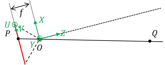
Firstly, the coordinate of camera has been established by the center of light as the original point $O$, and the direct of $X$ and $Y$ are the two directions of CCD pixel arrangement. The direct of $Z$ could be corrected by the right hand coordinate. Secondly, the coordinate of image established as two dimensions as the directions $U$ and $V$.
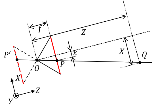
From the center of light $O$, the plane of image at $Z = f $, where $f$ is the physical focal length (unit: mm).
Point Q is in the space, which location is $Q(X,Y,Z)$ in the coordinate of camera.
Point P is in the plane of image, and it has two same description, like position $(x,y,f)$ in the coordinate of image plane and position $(u{ccd},v{ccd})$ in coordinate of pixel arrangement.
$k$ and $l$ are the length of two directions of one CCD pixel (unit: mm/pixel), so the definition of focus length are $f_x=\frac{f}{k}$ and $f_y=\frac{f}{l}$ (Unit: pixel).
If the offsets from the original point of the coordinate to the light axial are $c_x$ and $c_y$ (unit: pixel)
So the map between the position in pixel $(u{ccd},v{ccd})$ and the position in three dimensional space $(X, Y, Z)$ Is:
The Purpose of Camera Calibration
The purpose of the calibration process is to find the matrix $K\in\R^3$, the rotation matrix $R\in\R^3$, and the translation vector $t\in\R^3%=$ using a set of known 3D points $(X_w, Y_w, Z_w)$ and their corresponding image coordinates $(u,v)$. When we get the values of intrinsic and extrinsic parameters the camera is said to be calibrated.
In summary, a camera calibration algorithms has the following inputs and outputs
- Inputs: A collection of images with points whose 2D image coordinates and 3D world coordinates are known.
- Outputs: The camera intrinsic matrix, the rotation and translation of each image.
Different Types of Camera Calibration Methods
- Calibration pattern, Geometric clues, Deep Learning based
Camera Calibration Step by Step
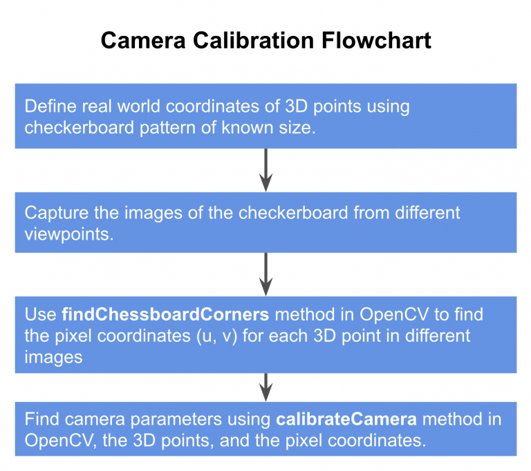
Step 1: Define real world coordinates with checkerboard pattern
World Coordinate System: In the calibration, the world coordinates are fixed by this checkerboard pattern that is attached to a wall in the room. Any corner of the above board can be chosen to the origin of the world coordinate system. The $X{w}$ and $Y{w}$ axes are along the wall, and the $Z{w}$ axis is perpendicular to the wall. All points on the checkerboard are therefore on the XY plane (i.e. $Z{w}=0$).
In the process of calibration we calculate the camera parameters by a set of know 3D points $(X{w}, Y{w}, Z_{w})$ and their corresponding pixel location $(u,v)$ in the image.
For the 3D points we photograph a checkerboard pattern with known dimensions at many different orientations. The world coordinate is attached to the checkerboard and since all the corner points lie on plane, we can arbitrarily choose $Z_{w}$ for every point to be 0.
Why is the ckeckerboard pattern so widely used in calibration?
Checkerboard patterns are distinct and easy to detect in an image. Not only that, the corners of squares on the checkerboard are ideal for localizing them because they have sharp gradients in two directions.
Step 2: Capture multiple images of the checkerboard from different viewpoints
Next, we keep the checkerboard static and take multiple images of the checkerboard by moving the camera. Alternatively, we can also keep the camera constant and photograph the checkerboard pattern at different orientations.
Step 3: Find 2D coordinates of checkerboard
We now have multiple of images of the checkerboard. We also know the 3D location of points on the checkerboard in world coordinates. The last thing we need are the 2D pixel locations of these checkerboard corners in the images.
3.1 Find checkerboard corners
OpenCV provides a builtin function called findChessboardCorners that looks for a checkerboard and returns the coordinates of the corners. Its usage is given by
C++
1 | |
Python
1 | |
Where, image is the source chessboard view (an 8-bit grayscale or color image), patternSize is the number of inner corners per a chessboard row and column ( patternSize = cvSize (points_per_row, points_per_colum) = cvSize(columns, rows)), corners is the output array of detected corners, and flags are the various operation flags.
3.2 Refine checkerboard corners
Good calibration is all about precision. To get good results, it is important to obtain the location of corners with sub-pixel level of accuracy. The function cornerSubPix takes in the original images, and the location of corners, and looks for the best corner location inside a small neighborhood of the original location.
C++
1 | |
Python
1 | |
Where, image is the imput image, corners are the initial coordinates of the input corners and refined coordinates provided for output, winSize is the half of the side length of the search window, zeroZone is the half of the size of the dead region in the middle of the search zone owver which the summation in the formula below is not done, and criteria is for the termination of the iterative process of corner refinement.
Step 4: Calibrate Camera
The final step of calibration is to pass the 3D points in world coordinates and their 2D locations in all images to calibrateCamera method.
C++
1 | |
Python
1 | |
Where, objectPoints is a vector of vectors of 3D points, ImagePoints is a vector of vectors of the 2D image points, ImageSize is the size of the image, cameraMatrix is the intrinsic camera matrix, distCoeffs is the lens distortion coefficients, rvecs is the rotation specified as a 3$\times$1 vector, and tvecs is the 3$\times$1 vector.
Camera Calibration Code
C++ Code
1 | |
Python Code
1 | |