Hand-eye_Calibration
Hand-eye Calibration
1. Introduction
Whenever a sensor is mounted on a robot arm it is important to know the relationship between the sensor and the hand. The problem of determining this relationship is referred to as the hand-eye calibration problem. Hand-eye calibration is important in at least two types of tasks:
Map sensor centered measurements into the robot workspace frame: For the task of grasping an object at an unknown location. Firstly, an object recognition system determines the position and orientation of the object with respect to the sensor; Secondly, the object location (position and orientation) is mapped from the sensor frame to the gripper (hand) frame. The robot may now direct its gripper towards the object and grasp it.
Allow the robot to precisely move the sensor: This is necessary for inspecting complex 3-D parts, for reconstructing 3-D scenes with a moving camera, or for visual servoing.
1.1 Regulation
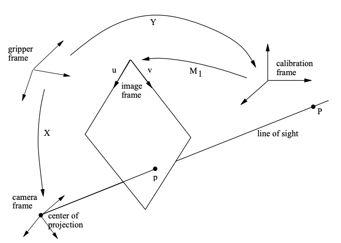
$X$ (gripper2camera): It represents the transform relationship between the gripper frame and the camera frame. (unknown)
$Y$ (gripper2calibration): It represents the transform relationship between the gripper frame and the calibration frame. (The desired result)
$M_1$ (the perspective matrix): It represents the external coefficients of camera. (known)
Suppose control the robot arm to move from the start position to the other position 1, there are following equations:
Then, combining above equations,
And the euqation will be changed by moving to the other position 2,
Because the base frame and the object frame in world is fixed and unchangable, thus the transform matrix between the base and object can be described by,
Abstract the above equations as,
And there are two possible formulations of the hand-eye calibration problem. One formulation is the classical one that we just mentioned. A second formulation takes the form of the following homogeneous matrix equation:
The advantage of the latter formulation is that the extrinsic and intrinsic parameters of the camera need not be made explicit. Indeed, this formulation directly uses the $3\times4$ perspective matrices ($M$ and $M’$) associated with 2 positions of the camera with respect to the calibration frame.
2. Problem Formulation
The hand-eye calibration problem consists of computing the rigid transformation (rotation and translation) between a sensor mounted on a robot actuator and the actuator itself, i.e., the rigid transformation between the sensor frame and the actuator frame.
2.1 The Classical Formulation
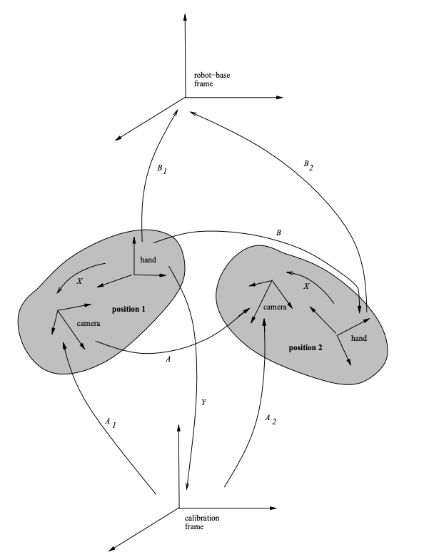
The hand-eye problem is best described on Figure 2. Let position 1 and position 2 be two positions of the rigid body formed by a sensor fixed onto a robot hand and which will be referred to as the hand-eye device. Both the sensor and. the hand have a Cartesian frame associated with them. Let $A$ be the transformation between the two positions of the sensor frame and let $B$ be the transformation be the transformation between the two positions of the hand frame. Let $X$ be the transformation between the hand frame and the sensor frame. $A$, $B$, and $X$ are related by the formula given by equation and they are $4\times 4$ matrices of the form:
And in the particular case of a camera-based sensor, the matrix $A$ is obtained by calibrating the camera twice with repect to a fixed calibrating object and its associated frame, called the calibration frame. Let $A_1$ and $A_2$ be the transformations from the calibration frame to the camera frame in its two different positions. We have $A = A_2\cdot A_1^{-1}$, the matrix $B$ is obtained by moving the robot hand from position 1 to position 2. Let $B_1$ and $B_2$ be the transformations from the hand frame in positions 1 and 2, to the robot-base frame. We have $B = B_2^{-1}\cdot B$
2.2 The New Formulation
The previous formulation implies that the camera is calibrated at each different position $i$ of the hand-eye device. Once the camera is calibrated, its extrinsic parameters, namely the matrix $A_i$ for position $i$, are made explicit. This is done by decomposing the $3\times4$ perspective matrix $M_i$, that is obtained by calibration, into intrinsic and extrinsic parameters:
The parameters $a_u$, $a_v$,$u_0$ and $v_0$ describe the affine transformation between the camera frame and the image frame. This decomposition assumes that the camera is described by a pin-hole model and that the optical axis associated with this model is perpendicular to the image plane.
Refer to the Figure 2, let $Y$ be the transformation matrix from the hand frame to the calibration frame, when the hand-eye device is position 1. Clearly we have $X = A_1\cdot Y$. Thus, matrix $Y$ is equivalent to matrix $X$, up to a rigid transformation $A_1$. By substituting $X$ given by this last equation, we obtain $A_2\cdot Y = A_1\cdot Y\cdot B$. By pre multiplying the terms of this equality with matrix $C$ and obtain $M_2\cdot Y = M_1\cdot Y \cdot B$.
Referring to Figure 2, the projection of a point $P$ onto the image is described by:
The determination of the hand-eye calibration allows one to express any line of sight associated with an image point $p$ in the hand frame and hence, in any robot centered frame.