This post record how to use the SOFA and the SoftRobots plugin in order to simulate a soft robot. The first part is dedicated to the set up of the simulation environment and the modeling of a virtual soft robot. Then, this post deals with the control of the real robot associated with the simulation.
Once completed, the knowledge acquired from this post on the robot called “Tripod” can be applied to other soft robots, thanks to the high modularity of SOFA.
Tutorial Requirements:
You have installed SOFA with the STLIB and SoftRobots plugins.
You have basic knowledge of the Python programming language.
You have basic knowledge of scene modeling with SOFA
This soft robot considered here is actuated by three servomotors connected to a deformable silicone material. Each of them controls the deformation of one ‘arm’ of the silicone piece. By combining the effects of the three servomotors, it is possible to control the shape of the whole deformable part, which benefits from a theoretically infinite number of degrees of freedom.
Reminder of SOFA’s GUI:
Once a scene is loaded in SOFA, you can click on the [Animate] button in the SOFA GUI to start the simulation. Once you have clicked anywhere on the 3D window and with the robot: depending on what was programmed, you can control the simulation to manipulated the robot, or interact with it by pressing Ctrl+Keys. Moreover, please note that, in order to send data to the robot, it can be necessary to have administrator rights.
Details
STEP 1: Building the Mechanical Model for the soft part & its Visual Model
At the end of this step, you will be able to:
Build the mechanical model of the silicone piece of the robot
Build the corresponding visual object
Use meshes for the mechanical description of a soft object
Reminder of the First Steps tutorial:
All the objects simulated in a scene are described in nodes attached to the main node rootNode. For this robot, there will be different objects, including one for silicone piece (ElasticBody). Each of them is defined with the function node.createChild()
In order to automatically reload the scene when changes made, run the scene with the -i option.
The properties of any object can be accessed by double-clicking on it in the Graph panel of the SOFA GUI.
By right-clicking in the Graph panel, the code file can be opened (Open file in editor in the drop-down menu).
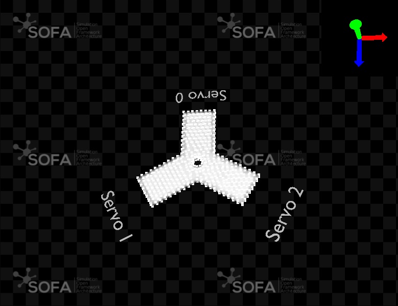
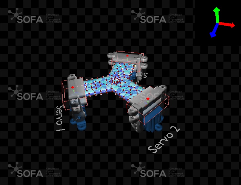
The first two steps aim at modeling the deformable silicone piece of the robot. The objects composing it are added one by one with the function node.createObject(). A mechanical model of the piece is first created, called ElasticBody. As the silicone piece is soft and can be deformed through constraints, it is necessary to describe its entire volume (and not only its center of gravity as it is usually done for rigid objects). Based on its shape, it is discretized: here it is decomposed into tetrahedral elements, linking all the points - or nodes - of the volume. This discretization produces the following types of elements: tetrahedrons, triangles, lines, and points. These elements are listed into a MechanicalObject named "dofs". The mesh file describing the discretization into tetrahedral element is "tropod_mid.stl". The data provided by the meshes must be organized and stored into different data fields (one for the positions of the nodes, one for the triangular elements, …) before SOFA uses them for computation. This formatting is done by means of code blocks called loaders. The loader used here, MeshSTLLoader is designed for STL files.
The mass distribution of the piece is implemented, as well as time integration scheme (implicit Euler method) and a solver (here the quick resolution method using the LDL matrix decomposition).
Then, a Visual model of the piece is built, using the same mesh file as for the mechanical model. Because it was decided (for the sake of simplicity) to use the same meshing for both models, the loader is introduced in the rootNode.
Finally, the two representations are linked together by a mapping, which allows to adapt the visual model to the deformations of the mechanical model of the soft piece. As the same mesh is used for both the mechanical and the visual model, the mapping is simply mirroring the mechanical model to adapt the visual one. This is why we use an IdentityMapping here.
defcreateScene(rootNode): # Setting the parameters: Gravity, Assuming the length unit is in millimeters. scene = Scene(rootNode, gravity=[0.0, -9810, 0.0], plugins=['SofaparseSolver', 'SofaOpenglVisual'], iterative=False) scene.addMainHeader() scene.addObject('DefaultAnimationLoop') scene.addObject('DefaultVisualmanagerLoop')
# Setting the parameters: Timestep in seconds rootNode.dt = 0.01
# Graphic Modeling of the legends associated to the servomotors blueprint = Sofa.Core.Node('Blueprints') blueprint.addObject('MeshSTLLoader', name='loader', filename='data/mesh/blueprint.stl') blueprint.addObject('OglModel', src='@loader') scene.Settings.addChild(blueprint)
# Tool to load the mesh file of the silicone piece. It will be used for both the mechanical and the visual models. scene.Modelling.addObject('MeshSTLLoader', name='loader', filename='data/mesh/tripod_mid.stl')
# Basic mechanical modeling of the silicone piece elasticbody = scene.Modelling.addChild('MechanicalModel') elasticbody.addObject('MechanicalObject', name='dofs', position=scene.Modelling.loader.position.getLinkPath(), showObject=True, showObjectScale=5.0, rotation=[90.0, 0.0, 0.0]) elasticbody.addObject('UniformMass')
# Visual object visual = scene.Modelling.addChild('VisualModel') # The mesh used for the Visual object is the same as the one for the MechanicalObject, #and has been introduced in the rootNode visual.addObject('OglModel', name='renderer', src=scene.Modelling.loader.getLinkPath(), color=[1.0, 1.0, 1.0, 0.5])
# A mapping applies the deformations computed on the mechanical model (the input parameter) # to the visual model (the output parameter) visual.addObject('IdentityMapping', input=elasticbody.dofs.getLinkPath() output=visual.renderer.getLinkPath()) scene.Simulation.addChild(scene.Modelling)
Exploring the scene
Try to orient the object differently on the 3D window by modifying its properties. Step 1 of the tutorial can be used as a guideline.
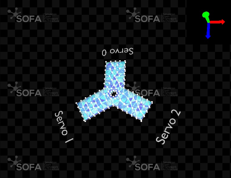
In the View panel of SOFA GUI, by enabling the Options, you can see the discretization of the silicone piece into tetrahedral elements.
Identify the white squares, each representing one point (one degree of freedom) of the MechanicalObject, on which the deformations are computed.
Remarks
SOFA implements default length and time units, as well as a default gravity force. The user defines his own time and space scale by defining the constants of the model. Here, the gravity of our simulation is defined such as the length unit is in centimeters; and the time unit chosen is the second, which means that the time step is of one millisecond.
There is a graphic modeling in the scene to display the legends associated with the servomotors, that are described in the file blueprint.stl.
STEP 2: Modeling the possible deformations of the soft material
At the end of this step, you will be able to:
Build an elastic deformation model based on the Finite Element Method
Understand what a ForceFieldis
Unlike the rigid objects modeled in the First Steps tutorials, the silicone piece is deformable, and as such, requires additional components describing the behavior of the material when it is submitted to mechanical constraints.
In order to implement the deformation behavior, the MechanicalObject must be connected to one or multiple ForceFileds. These ForceFields are in charge of computing the internal forces that will guide the deformation of the soft piece. Many different mechanical behaviors exist and it is important to understand the one that best approximates the behavior of the real object. In particular, it is important to know how soft or stiff the material is, as well as if it has an elastic behavior or a more complex one (hyperelastic, plastic, etc…). In our case, it has been chosen to implement a law of elastic deformation, modeled using the Finite Element Method(FEM). Its parameters are the Young modulus, and the Poisson ratio.
In SOFA, the ElasticMaterialObject from stlib3.physics.deformable provides a ready to use prefabricated object to easily add such an object in our scene. It defines the whole mechanical model of a deformable elastic object.
However, before using this prefabricated object, let’s first build our own, based on a corotational Finite Element Method with a tetrahedral volumetric representation of the shape. The mesh tripod_mid.gidmsh used to store the shape of the deformable object was built with the GiD mesh generator. Starting from the model obtained in the last step, the parameters of the elastic deformation are added to the silicone piece with a ForceField component.
# It is possible to visualize the 'forcefields' by doing scene.VisualStyle.displayFlags = 'showForceFields'
# Change the stiffness of the spring while interacting with the simulation scene.Settings.mouseButton.stiffness = 1.0
# Graphic modelling of the legends associated to the servomotors blueprint = Sofa.Core.Node("Blueprints") blueprint.addObject('MeshSTLLoader', name='loader', filename='data/mesh/blueprint.stl') blueprint.addObject('OglModel', src='@loader') scene.Modelling.addChild(blueprint)
# To simulate an elastic object, we need: # - a deformation law (here linear elasticity) # - a solving method (here FEM) # - as we are using FEM we need a space discretization (here tetrahedron) elasticbody = scene.Modelling.addChild('ElasticBody')
# Specific loader for the mechanical model elasticbody.addObject('GIDMeshLoader', name='loader', filename='data/mesh/tripod_low.gidmsh') elasticbody.addObject('TetrahedronSetTopologyContainer', src='@loader', name='tetras')
Add constraints on specific areas through the use of the Fixing Box ROI prefab
Understand how the Fixing Box is implemented
Build functions to bring together all the components of an object
In this step, the prefab FixingBox is described, that allows to fix the position of some areas of a physical object in space. (ROI stands for Region Of Interest.) It will be used in this step to prevent the falling of the silicone piece under gravity, by constraining the position of its central part. The prefab object is called via the following function:
In parallel, in order to lighten the code and ease the reading, the introduction of a function ElasticBody(parent) is proposed in this step, bringing together all the components of the silicone piece model. This function also uses the prefab ElasticMaterialObject, that implements the mechanical model of an elastic material (including a mesh loader, mass definition, time integration and solver tools, and the description of the Force Fileds).
Such a function is defined at the beginning of the scene, and can be called as often as wished in the description of the scene (i.e. in the function createScene(rootNode)).
The constraint implemented by the FixingBox prefab, named RestShapeSpringForceField, applies in fact elastic spring forces on the points of the mechanical object (the degrees of freedom) included in the FixingBox, to bring them back to their resting position whenever a modifications is computed (due to gravity forces for example). The stiffness of these ‘springs’ is set at a very hight level, which produces immediate correction of any change in position: the constrained points cannot move anymore.
The box can be moved anywhere to constraint another area. For example, the translation [30.0, 0.0, 30.0] allows to constraint the end of the arm connected to servo 2.
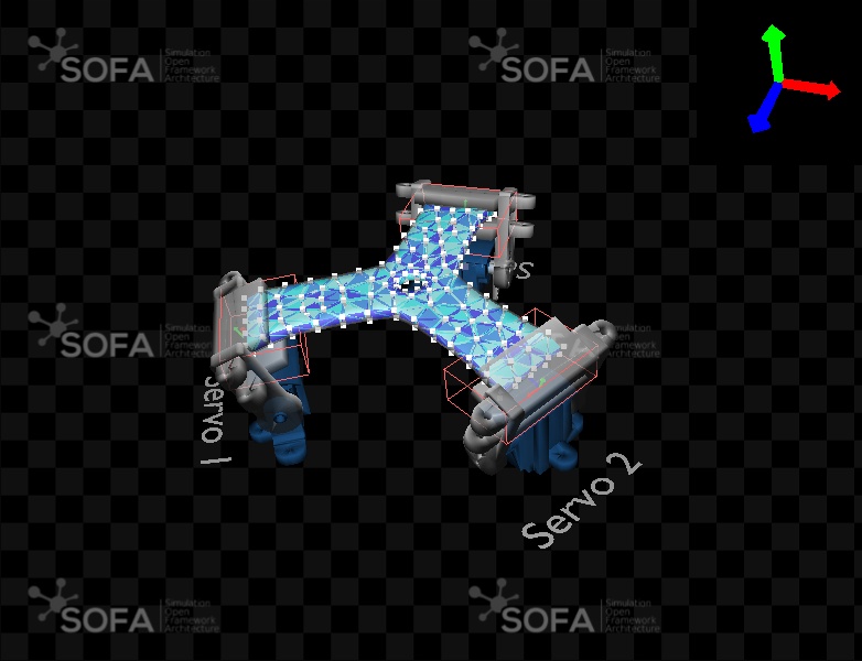
By clicking on the [Animate] button, ti can be observed that the FixingBox indeed prevents the silicone piece to fall under gravity force. The unconstrained tips of the piece, however, experience a light bending.
It is possible to deform the silicone piece with the mouse, by pressing Maj while left-clicking on the piece, dragging the mouse. This can be used to observe how elastic the material is. By changing the value of the young modulus, you can compare the rendering of the simulated piece with the real one (for example, test values from 10 to 2000 for the Young modulus after having manipulated the silicone piece on the real robot abit, to get an idea of its elasticity).
STEP 4: Adding actuators and connecting to deformable part
At the end of this step, you will be able to:
Add prefabs for the actuators (STEP 4-1)
Rigidify some parts of the deformable model (STEP 4-2)
Attach the rigidify parts to the actuators (STEP 4-3)
STEP 4-1: Adding actuators
At the end of this step, you will be able to:
Add prefabs for the actuators
Position them according to the real robot positioning
Understand the structure of the prefabs modeling the S90 servomotors and the associated servo-arms used on the Tripod robot: ServoMotor, ServoArm and the prefab ActuatedArm that brings the first two together.
Understand another graph structure for the objects of the scene, by introducing the object Simulation.
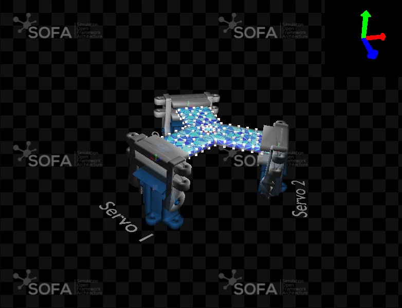
It is now time to add the actuators that will deform the elastic piece. On the real robot, this is done by 3 servomotors actuating servo-arms attached to the silicone piece. On SOFA, two prefabricated objects have been implemented and brought together in a third one named ActuatedArm. The two elements composing it can be seen on Figure below. The prefabs are described in a python file, that contains all the elements of the model of the object. They are imported at the beginning of the code file of the scene, and can then be used in the scene. The lines to import the ServoArm and the ActuatedArm prefab are the following:
1
2
from actuatedarm import ActuatedArm
from tripod import ElasticBody
actuatedarm and tripod (as well as s90servo that is used in the actuatedarm file) are the names of the python scripts that describe the prefabs. They are located in the folder details of the Tripod tutorial.
The prefab ActuatedArm is building up the ensemble composed of a servomotor and a servo-arm, and includes a Fixing Box situated at the tip of the servo-arm, that attaches the silicone piece to the servo-arm.
It uses the prefabs ServoMotor and ServoArm, that are described as rigid objects and implemented in the files s90servo.py and actuatedarm.py respectively. By opening those files, you will see that the prefabs are actually defined as classes. At the end of the file, you can find a small scene in the function createScene() that provides an example of use of the prefab.
The mechanical model of the ServoMotor and the ServoArm is described in their prefab, but it doesn’t include a time integration scheme nor a solver. In the previous steps, these were added in the object’s node. However, in this step, a different organization is proposed: the mechanical & visual models of the objects are created on one side, grouped in a node called Tripod; and a node ‘Simulation’ is built on the other side, that implements time integration and a solving tool, and links them to their corresponding object. This linking is done thanks to the object Scene from the file tutorial.py located in the same directory, that is also imported at the beginning of the code file.
Just like for the ElasticBody, a function Tripod() is introduced, now that all the pieces of the robot have been modelled:
import Sofa from tutorial import * from splib3.numerics import sin, cos, to_radians from actuatedarm import ActuatedArm from elasticbody import ElasticBody from blueprint import Blueprint
self = Sofa.Core.Node(name) self.actuatedarms = [] for i inrange(0, numMotors): name = "ActuatedArm" + str(i) translation, eulerRotation = __getTransform(i, numMotors, angleShift, radius, radius) arm = ActuatedArm(name=name, translation=translation, rotation=eulerRotation)
# Add limits to angle that correspond to limits on real robot arm.ServoMotor.minAngle = -2.0225 arm.ServoMotor.maxAngle = -0.0255 self.actuatedarms.append(arm) self.addChild(arm)
## Add animations defmyanimate(targets, factor): for arm in targets: arm.angleIn.value = -factor * math.pi / 4 animate(myanimate, {"targets": [tripod.ActuatedArm0, tripod.ActuatedArm1, tripod.ActuatedArm2]}, duration=1)
Exploring the scene
Explore the Info panel in the window that appears when double-clicking on the different components: you can observe that the prefab objects propose some documentation and a description of specific properties
Explore the hierarchy of the nodes in the Graph panel, to observe the structure of the ActuatedArm prefab. More particularly, in the ServoMortor prefab of each ActuatedArm, a ServoWheel prefab can be seen. It represents the capability - or degree of freedom - of the servo-arm to rotate around the motor shaft. It is implemented in the file s90servo.py and composed of a Rigid MechanicalObject, on which the rotations are applied, and then transferred to the ActuatedArm on which the ServoWheel is attached
My modifying the EulerRotation and translation parameters of the ActuatedArm instances, try to constrain different parts of the model.
Remarks
Different solvers have been used so far: SparseLDLSolver for the former steps, and here, the CGLinearSolver (using the Conjugate Gradient Method) introduced in the Simulation object. The difference in the results of the simulation, depending on the solver used is negligible in the scenes presented in this tutorial.
However, the solving methods sometimes have properties that allow particular manipulations of the objects in the scene. By using the CGLinearSolver for the servomotors, it is possible to move the servomotor base in the simulation window by holding the Shift key while left-clicking on the servo base to drag it. This shows the connection with the silicone piece, that follows the movement, like it would with the real robot.
Note that the same Shift + Click and drag manipulation isn’t possible on the servo-arm alone. Indeed, since the arm is constrained by the servomotor, trying to move it away from the servomotor would produce a conflict situation and the system would diverge.
from splib3.numerics import to_radians from stlib3.physics.mixedmaterial import Rigidify from stlib3.components import addOrientedBoxRoi from splib3.numerics import vec3 from splib3.numerics.quat import Quat from tutorial import * from actuatedarm import ActuatedArm from elasticbody import ElasticBody from blueprint import Blueprint
box = addOrientedBoxRoi(self, position=[list(i) for i in deformableObject.dofs.rest_position.value], name="BoxROI" + str(i), translation=vec3.vadd(translation, [0.0, 25.0, 0.0]), eulerRotation=eulerRotation, scale=[45, 15, 30])
box.drawBoxes = False box.init() groupIndices.append([ind for ind in box.indices.value]) frames.append(vec3.vadd(translation, [0.0, 25.0, 0.0]) + list( Quat.createFromEuler([0, float(i) * 360 / float(numstep), 0], inDegree=True)))
# Rigidify the deformable part at extremity to attach arms rigidifiedstruct = Rigidify(self, deformableObject, groupIndices=groupIndices, frames=frames, name="RigidifiedStructure")
self = Sofa.Core.Node(name) self.actuatedarms = [] for i inrange(0, numMotors): name = "ActuatedArm" + str(i) translation, eulerRotation = __getTransform(i, numMotors, angleShift, radius, radius) arm = ActuatedArm(name=name, translation=translation, rotation=eulerRotation)
# Add limits to angle that correspond to limits on real robot arm.ServoMotor.minAngle = -2.0225 arm.ServoMotor.maxAngle = -0.0255 self.actuatedarms.append(arm) self.addChild(arm)
# Use this to activate some rendering on the rigidified object ###################################### setData(tripod.RigidifiedStructure.RigidParts.dofs, showObject=True, showObjectScale=10, drawMode=2) setData(tripod.RigidifiedStructure.RigidParts.RigidifiedParticules.dofs, showObject=True, showObjectScale=1, drawMode=1, showColor=[1., 1., 0., 1.]) setData(tripod.RigidifiedStructure.DeformableParts.dofs, showObject=True, showObjectScale=1, drawMode=2) #####################################################################################################
# Temporary additions to have the system correctly built in SOFA # Will no longer be required in SOFA v22.06 scene.Simulation.addObject('MechanicalMatrixMapper', template='Vec3,Rigid3', name="RigidAndDeformableCoupling", object1=tripod.RigidifiedStructure.DeformableParts.dofs.getLinkPath(), object2=tripod.RigidifiedStructure.RigidParts.dofs.getLinkPath(), nodeToParse=tripod.RigidifiedStructure.DeformableParts.MechanicalModel.getLinkPath())
STEP 4-3: Attach the actuators to the deformable piece
from splib3.numerics import to_radians from stlib3.physics.mixedmaterial import Rigidify from stlib3.components import addOrientedBoxRoi from splib3.numerics import vec3 from splib3.numerics.quat import Quat from tutorial import * from actuatedarm import ActuatedArm from elasticbody import ElasticBody from blueprint import Blueprint
box = addOrientedBoxRoi(self, position=[list(i) for i in deformableObject.dofs.rest_position.value], name="BoxROI" + str(i), translation=vec3.vadd(translation, [0.0, 25.0, 0.0]), eulerRotation=eulerRotation, scale=[45, 15, 30])
box.drawBoxes = False box.init() groupIndices.append([ind for ind in box.indices.value]) frames.append(vec3.vadd(translation, [0.0, 25.0, 0.0]) + list( Quat.createFromEuler([0, float(i) * 360 / float(numstep), 0], inDegree=True)))
# Rigidify the deformable part at extremity to attach arms rigidifiedstruct = Rigidify(self, deformableObject, groupIndices=groupIndices, frames=frames, name="RigidifiedStructure")
def__attachToActuatedArms(self, numstep): rigidParts = self.RigidifiedStructure.RigidParts for arm in self.actuatedarms: arm.ServoMotor.Articulation.ServoWheel.addChild(rigidParts)
self = Sofa.Core.Node(name) self.actuatedarms = [] for i inrange(0, numMotors): name = "ActuatedArm" + str(i) translation, eulerRotation = __getTransform(i, numMotors, angleShift, radius, radius) arm = ActuatedArm(name=name, translation=translation, rotation=eulerRotation)
# Add limits to angle that correspond to limits on real robot arm.ServoMotor.minAngle = -2.0225 arm.ServoMotor.maxAngle = -0.0255 self.actuatedarms.append(arm) self.addChild(arm)
# Temporary additions to have the system correctly built in SOFA # Will no longer be required in SOFA v22.06 for i inrange(3): scene.Simulation.addObject('MechanicalMatrixMapper', name="ArmAndDeformableCoupling" + str(i), template='Vec1,Vec3', object1=tripod["ActuatedArm" + str(i) + ".ServoMotor.Articulation.dofs"].getLinkPath(), object2=tripod["RigidifiedStructure.DeformableParts.dofs"].getLinkPath(), skipJ2tKJ2=Falseif i == 0elseTrue, nodeToParse=tripod.RigidifiedStructure.DeformableParts.MechanicalModel.getLinkPath())
STEP 5: Adding controllers
At the end of this step, you will be able to:
Implement a controller for interactive change of the servomotors angular position with keyboard keys
Define an animation function, that acts on the actuators by translating & rotating them
The servomotors have a default angular position, that corresponds to an angle of 180 degree. To interactively change this default position, a dedicated object will be added, called a Controller. Controllers allow to implement custom behavior and end-user interaction directly, using python.
In this step we are adding such a controller, in order to be able to control the position of each servo-arm with keyboard keys. On the real robot, the initial position considered is the one when the silicone piece is laying flat, which means that the servomotors are at an angle of 90 degree.
The keys involved in the control and the effect they trigger are described below:
The following combinations allow to control the angular position of the servomotors, seqparately.
Keyboard keys
Effect on angle
For Servo
Ctrl+UP
Increase
0
Ctrl+DOWN
Decrease
0
Ctrl+LEFT
Increase
1
Ctrl+RIGHT
Decrease
1
Ctrl+PLUS
Increase
2
Ctrl+MINUS
Decrease
2
SOFA allows a default animation management: this is what was being used up to now. In this step, we want to add a more specific animation that updates the scene at each time step, depending on the keys pressed by the user. The control of this animation is done thanks to a python script controller (class CONTROLLER_NAME(SOFA.Core.Controller)) that is added in our scene file. It uses the function (or method) onKeypressedEvent() that is included in SOFA by default and that triggers an action if a designated key is pressed. The controller is implemented such as, after each key press, the designated servomotor moves from a stepsize value of 0.1 rad (that is a little less than 6 degree) by changing the value of the attribute ServoMotor.angleIn.
Moreover, another animation is added in the function setupanimation(actuators, step, angularstep, factor), in order to move with one keystroke the three servomotors from their default angular position to the initial position of the real robot. It is triggered by the Ctrl+A.
The animation is implemented, using the function animate(cb, params, duration) from the STLIB plugin, and the function setupanimation(actuators, step, angularstep, factor). The animate function calls setupanimation and provides the structure of the animation: a small variation of the parameters (step value) is computed each time that the setupanimation function is called; the animate function is a recursive function, that calls itself over and over again, as long as the duration value hasn’t been reached.
import Sofa from stlib3.scene import Scene #< Prefab for the scene from tripod import Tripod #< Prefab for the Tripod from tripodcontroller import TripodController #< Implementation of a controller that modify the Tripod
classMyController(Sofa.Core.Controller): def__init__(self, *args, **kwargs): # These are needed (and the normal way to override from a python class) Sofa.Core.Controller.__init__(self, *args, **kwargs)
# Temporary additions to have the system correctly built in SOFA # Will no longer be required in SOFA v22.06 scene.Simulation.addObject('MechanicalMatrixMapper', name="deformableAndFreeCenterCoupling", template='Vec3,Rigid3', object1=tripod["RigidifiedStructure.DeformableParts.dofs"].getLinkPath(), object2=tripod["RigidifiedStructure.FreeCenter.dofs"].getLinkPath(), nodeToParse=tripod["RigidifiedStructure.DeformableParts.MechanicalModel"].getLinkPath())
for i inrange(3): scene.Simulation.addObject('MechanicalMatrixMapper', name="deformableAndArm{i}Coupling".format(i=i), template='Vec1,Vec3', object1=tripod["ActuatedArm" + str(i) + ".ServoMotor.Articulation.dofs"].getLinkPath(), object2=tripod["RigidifiedStructure.DeformableParts.dofs"].getLinkPath(), skipJ2tKJ2=True, nodeToParse=tripod["RigidifiedStructure.DeformableParts.MechanicalModel"].getLinkPath())
Exploring the scene
After clicking on the [Animate] button, and then anywhere in the simulation window, use the defined keystrokes to deform the silicone shape by controlling the angular position of the servomotors.
Try to implement a different animation, modifying the initial position of the angular position of the servomotors.
Remark
When the scene is loaded and animated, it can be interesting to display the execution time’s distribution between the different components of the simulation. For that purpose, activate the Log Time option in the Stats panel of the simulation window. The steps duration statistics appear then in the terminal window.
The most time consuming process - and thus the one requiring the greatest computing resources - is related to the computation of the Mechanical behavior, with more than half of the resources allocated to the solving tools. This highlights the complexity of the system and explains why the mesh cannot be endlessly tightened: the simulation would take a great amount of time to compute, too much for any real time application.
STEP 6: Adding collision models
At the end of this step, you will be able to:
Add a rigid object that interacts with the robot thanks to the collision model
Add a collision model so that the collision model can no longer go through the servomotors.
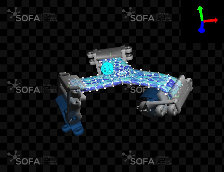
By default SOFA doesn’t handle collision as they are so expensive to compute. To activate collisions you need to define specifically the geometries for which collisions are checked and how they are handled. In this step, we are adding a rigid Sphere object falling on the robot, as well as the description of the contact management between the ball and the silicone piece. (This scene is defined for the simulation only, the interaction with the real robot has not been added.)
A new controller, called JumpController, is also added to change rapidly the servo motors angles so the robot can play with the falling ball.
The same keystrokes as in the previous steps are used, adding two new intermediate positions for a more dynamical response.
Keystroke to move the servomotors from their default position to the initial one of the real robot: Ctrl + A
Keystroke to position the servomotors to an intermediate position: Ctrl + Q
keystroke to position the servomotors to a high angular position: Ctrl + Z
import Sofa from splib3.constants import Key from stlib3.physics.rigid import Sphere from stlib3.scene.contactheader import ContactHeader from stlib3.scene import Scene from tripod import Tripod from tripodcontroller import TripodController
classJumpController(Sofa.Core.Controller): """This controller has two roles: - if the user presses up/left/right/down/plus/minus, the servomotor angle is changed. - if the user presses A, an animation is started to move the servomotor to the initial position of the real robot. """ def__init__(self, *args, **kwargs): # These are needed (and the normal way to override from a python class) Sofa.Core.Controller.__init__(self, *args, **kwargs) self.stepsize = 0.1 self.actuators = kwargs["actuators"]
# The regular controller that is being used for the last 2 steps controller = scene.addObject(TripodController(name="TripodController", actuators=[tripod.ActuatedArm0, tripod.ActuatedArm1, tripod.ActuatedArm2])) # You can set the animation from the python script by adding this call controller.initTripod('A')
# The additionnal controller that add two predefined positions for the three servomotors scene.addObject(JumpController(name="JumpController", actuators=[tripod.ActuatedArm0, tripod.ActuatedArm1, tripod.ActuatedArm2]))
# Temporary additions to have the system correctly built in SOFA # Will no longer be required in SOFA v22.06 scene.Simulation.addObject('MechanicalMatrixMapper', name="deformableAndFreeCenterCoupling", template='Vec3,Rigid3', object1=tripod["RigidifiedStructure.DeformableParts.dofs"].getLinkPath(), object2=tripod["RigidifiedStructure.FreeCenter.dofs"].getLinkPath(), nodeToParse=tripod["RigidifiedStructure.DeformableParts.MechanicalModel"].getLinkPath())
for i inrange(3): scene.Simulation.addObject('MechanicalMatrixMapper', name="deformableAndArm{i}Coupling".format(i=i), template='Vec1,Vec3', object1=tripod["ActuatedArm" + str(i) + ".ServoMotor.Articulation.dofs"].getLinkPath(), object2=tripod["RigidifiedStructure.DeformableParts.dofs"].getLinkPath(), skipJ2tKJ2=True, nodeToParse=tripod["RigidifiedStructure.DeformableParts.MechanicalModel"].getLinkPath())
Exploring the scene
Once the scene animated, observe how the ball follows the movement of the silicone piece: as load as the ball sits into the small hole at the center of the silicone piece, it follows its movements. However, if the silicone piece is sloped enough, the ball falls under gravity force.
Thanks to the collision model between the top of the servomotors and the silicone piece, the silicone piece can no longer go through the servomotors.
STEP 7: Connecting to the physical robot
At the end of this step, you will be able to:
Connect the simulated robot to the real one.
Directly control the angular position of their real servomotors by actuating the simulated ones.
It is now time to connect our simulated robot to the real one. This requires the additions of two elements. The first one, SerialPortBridgeGeneric, is a component that defines how the communication through the USB/Serial port is handled; it is an object of the rootNode.
The second one, SerialPortController, is another Controller, reading the angular position of the simulated servomotors (in one of the data field) and sends them via the USB communication cable. The angular position of the simulated servomotors is stored in actuators[i].ServoMotor.angleIn in radian, and is transfered to the field serialport.packetOut of the controller board.
Because the data are now sent to the real robot, it is necessary to implement a limitation of the possible angular positions to be reached: between 60 and 180 degrees. Any angle outside this interval is limited to the interval’s extreme value instead.
The keystrokes implemented are the same as for the previous steps, adding one to start sending data to the robot.
Keystroke to start sending data to the real robot: Ctrl + B
Keystroke to move the servomotors from their default position to the initial one of the real robot: Ctrl + A
import Sofa from tutorial import * from splib3.animation import animate from splib3.constants import Key from math import floor, pi from tripod import Tripod from tripodcontroller import TripodController, setupanimation
classTripodControllerWithCom(TripodController): """This controller has three roles: - if the user presses up/left/right/down/plus/minus, the servomotor angle is changed. - if the user presses A, an animation is started to move the servomotor to the initial position of the real robot. - if thr user presses B start the communication with controller card, send servomotor commands """
# Inclusion of the keystroke to start data sending = establishing communication ('comm') if key == Key.B and self.serialportctrl.state == "no-comm": self.serialportctrl.state = "comm"
# Description of how the communication is handled # CHANGE HERE the serialport that correspond to your computer # def SerialPortBridgeGeneric(rootNode, serialport='/dev/cu.usbserial-1420'): # def SerialPortBridgeGeneric(rootNode, serialport='COM3'): defSerialPortBridgeGeneric(rootNode, serialport='/dev/ttyUSB0'): return rootNode.addObject('SerialPortBridgeGeneric', port=serialport, baudRate=115200, size=3, listening=True, header=255)
defonAnimateEndEvent(self, event): # Data sending if the robot is initializing or in the no-communication state if self.state == "init": return
if self.state == "no-comm": return
# Vector storing the simulated servomotors' angular position angles = []
for arm in self.actuatedarms: # Conversion of the angle values from radians to degrees angleDegree = arm.servomotor.angleOut.value * 360 / (2.0 * pi) angleByte = int(floor(angleDegree)) + 179
# Limitation of the angular position's command if angleByte < 60: angleByte = 60 if angleByte > 180: angleByte = 180
# Filling the list of the 3 angle values angles.append(angleByte) # The controller board of the real robot receives `angles` values self.serialport.packetOut = angles
defcreateScene(rootNode): from stlib3.scene import Scene scene = Scene(rootNode, gravity=[0., -9810., 0.], dt=0.01, iterative=False, plugins=["SofaSparseSolver", "SofaOpenglVisual", "SofaSimpleFem", "SoftRobots", 'SofaBoundaryCondition', 'SofaDeformable', 'SofaEngine', 'SofaGeneralRigid', 'SofaMiscMapping', 'SofaRigid', 'SofaGraphComponent', 'SofaGeneralAnimationLoop', 'SofaGeneralEngine'])
# The real robot receives data from the 3 actuators serialportctrl = scene.addObject( SerialPortController(name="SerialPortController", inputs=tripod.actuatedarms, serialport=serial))
# The simulation's control with keystrokes is still available controller = scene.addObject( TripodControllerWithCom(scene, actuators=tripod.actuatedarms, serialportctrl=serialportctrl)) # You can set the animation from the python script by adding this call controller.initTripod('A')
scene.Simulation.addChild(tripod)
# Temporary additions to have the system correctly built in SOFA # Will no longer be required in SOFA v22.06 scene.Simulation.addObject('MechanicalMatrixMapper', name="deformableAndFreeCenterCoupling", template='Vec3,Rigid3', object1=tripod["RigidifiedStructure.DeformableParts.dofs"].getLinkPath(), object2=tripod["RigidifiedStructure.FreeCenter.dofs"].getLinkPath(), nodeToParse=tripod["RigidifiedStructure.DeformableParts.MechanicalModel"].getLinkPath())
for i inrange(3): scene.Simulation.addObject('MechanicalMatrixMapper', name="deformableAndArm{i}Coupling".format(i=i), template='Vec1,Vec3', object1=tripod["ActuatedArm" + str(i) + ".ServoMotor.Articulation.dofs"].getLinkPath(), object2=tripod["RigidifiedStructure.DeformableParts.dofs"].getLinkPath(), skipJ2tKJ2=True, nodeToParse=tripod["RigidifiedStructure.DeformableParts.MechanicalModel"].getLinkPath())
Exploring the scene
Start the scene with the [Animate] button, then click anywhere in the simulation window and type the keystroke to start sending data to the real robot. Observe how the real robot responds to the modifications of the simulation: this is the direct control, where the user specifies the angular position to reach, which are then also sent to the robot.
Remark how the real robot is limited in his movements, while nothing prevents the user to make complete turns around the motor shaft with the servo-arms in the simulation.
STEP 8: Additional Modules
STEP 8.1: Inverse Control
In the previous steps we where controlling the robot by directly specifying the angle of the Servo Motor object. In this step we will use SOFA to inverse the model and adding a effector to the simulation so that it becomes possible to specify the effector’s position and let the simulation compute the angular positions to apply to reach the effector’s position.
The same keystrokes as in the previous steps are used, adding a new one to start the inverse resolution.
Keystroke to start sending data to the real robot: Ctrl + B
Keystroke to move the servomotors from their default position to the initial one of the real robot: Ctrl + A
Keystroke to start the inverse resolution: Ctrl + I
# Serial port bridge serial = SerialPortBridgeGeneric(rootNode)
# Choose here to control position or orientation of end-effector orientation = False if orientation: # inverse in orientation goalNode = EffectorGoal([0, 50, 50]) else: # inverse in position goalNode = EffectorGoal([0, 40, 0]) scene.Modelling.addChild(goalNode)
# The real robot receives data from the 3 actuators # serialportctrl = scene.addObject(SerialPortController(scene, inputs=tripod.actuatedarms, serialport=serial)) invCtr = scene.addObject(InverseController(scene, goalNode, actuators, tripod.ActuatedArm0.ServoMotor.Articulation.ServoWheel.RigidParts, tripod, serial, [tripod.ActuatedArm0, tripod.ActuatedArm1, tripod.ActuatedArm2]))
# The regular controller that is being used for the last 2 steps but with small additions scene.addObject(DirectController(scene, tripod.actuatedarms, invCtr))
scene.Simulation.addChild(tripod)
# Temporary additions to have the system correctly built in SOFA # Will no longer be required in SOFA v22.06 scene.Simulation.addObject('MechanicalMatrixMapper', name="deformableAndFreeCenterCoupling", template='Vec3,Rigid3', object1=tripod["RigidifiedStructure.DeformableParts.dofs"].getLinkPath(), object2=tripod["RigidifiedStructure.FreeCenter.dofs"].getLinkPath(), nodeToParse=tripod["RigidifiedStructure.DeformableParts.MechanicalModel"].getLinkPath())
for i inrange(3): scene.Simulation.addObject('MechanicalMatrixMapper', name="deformableAndArm{i}Coupling".format(i=i), template='Vec1,Vec3', object1=tripod["ActuatedArm" + str(i) + ".ServoMotor.Articulation.dofs"].getLinkPath(), object2=tripod["RigidifiedStructure.DeformableParts.dofs"].getLinkPath(), skipJ2tKJ2=True, nodeToParse=tripod["RigidifiedStructure.DeformableParts.MechanicalModel"].getLinkPath())
STEP 8.2: Defining a motion path for the maze
In the previous steps we where controlling the robot in inverse mode. We want now to make the robot follow a predefined path.
# Open maze planning from JSON file data = json.load(open('mazeplanning.json')) effector.addObject(MazeController(effector, data["anglePlanningTable"], True))