micro_ros
Micro-ROS on STM32 micro-controller
This is the unofficial tutorial for setting up the micro-ROS on STM32 micro-controller. I have successfully set up the micro-ROS on the STM32F446RET6 and tested with Ubuntu20.04. Following this tutorial, you could set up it on your own micro-controller, but for the arduino , you might refer some other references. In my opinion, there are the same one and it could be easily to find out the official document on the Github.
Introduction
Features
The Micro-ROS offers seen key features that make it ready for use in your micro-controller-based robotic project:
- Micocontroller-optimized client API supporting all major ROS concepts: Micro-ROS brings all major core concepts such as nodes, publish/subscribe, client/service, node graph, life-cycle, etc. onto microcontrollers (MCU). The client API of Micro-ROS is based on the standard ROS 2 Client Support Library (
rcl) and a set of extensions and convenience functions; - Seamless integration with ROS 2;
- Extremely resource-constrained but flexible middle ware;
- Multi-RTOS support with generic build system;
- Permissive license;
- Vibrant community and ecosystem;
- Long-term maintainability and interoperability;
Architecture
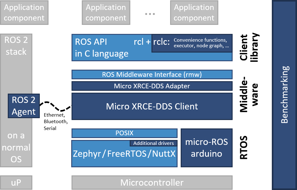
Micro-ROS follows the ROS 2 architecture and makes use of its middleware pluggability to use DDS-XRCE, which is optimized for microcontrollers. Moreoer, it uses POSIX-based RTOS(FreeRTOS, Zephyr, or NuttX) instead of Linux. Dark blue components are developed specially for Micro-ROS. Light blue components are taken from the standard ROS 2 stack.
Requirements
STM32 micro-controller (ex: Necleo STM32F446R6)
Linux PC with installed ROS 2
- STM32CubeMX
- STM32CubeIDE
Set up for Micro-controller
STMCubeMX: Generate Basic Code
Using STMCubeMX, we can initialize the pin with in the GUI. Specially, I setup the FreeRTOS, UART4, TIMER1, GPIOand basic pin initialized autonomously. Among them, the FreeRTOS is one of the real time control architecture, and I will use it to control the device in the real time mode. The UART4 is the connection protocol to the PC and it is the very high priority to interrupt. I use two channel of TIMER1 to generate PWM signal and control device. Then the GPIO is used to control the input signal of the switch circuit fabricated by transistor.

Then choose the generate mode with Makefile and do it.
Makefile
we need modify the generated Makefile to include the following code before the build operation:
1 | |
micro_ros_stm32cubemx_utils
This step, we need to clone the repository into the firmware location. And this repository is aims to ease the micro-ROS integration in a STM32CubeMX/IDE project.
Note: These commands must be run under the Firmware folder
1 | |
Then using the docker, to execute the static library generation tool. Compiler flags will retrieved automatically from our Makefile and user will be prompted to check if they are correct.
Note: These commands must be run under the Firmware folder
1 | |
After the installing process, you can find out the following output which means installed successfully.
1 | |